Design guides
DfAM Best Practices for 3D Printing
The essential rules of Design for Additive Manufacturing: wall thickness, orientation, overhangs, tolerances and topology optimization for each technology.
Design for Additive Manufacturing: practical best practices
DfAM (Design for Additive Manufacturing) is the discipline that adapts mechanical design to the constraints and freedoms of 3D printing. A "well-printed" component starts from a CAD model conceived for additive, not simply adapted from a drawing made for CNC.
1. Minimum wall thickness
Every technology has a physical limit below which a wall becomes fragile or cannot be built.
| Technology | Recommended minimum wall |
|---|---|
| FDM (high-performance polymers) | 3 mm |
| MSLA | 1 mm |
| SLS | 0.8 mm |
| CFC | 1.5 mm (to allow fiber deposition) |
Below these values, mechanical strength drops off nonlinearly.
2. Print orientation
Orientation is the variable with the greatest influence on the mechanical properties of FDM and CFC parts: strength is highest in the XY plane and lowest along Z (the interface between layers). Rules of thumb:
- Align load directions with the XY plane.
- Avoid critical surfaces facing downward (they require supports).
- For functional threads, orient the thread axis vertically.
3. Overhangs and supports
The typical critical angle is 45°: beyond it, supports are needed. Strategies to avoid them:
- Chamfers and fillets instead of overhanging surfaces.
- Horizontal holes reshaped as teardrop holes.
- Internal cavities designed with drainage channels for powder or resin (MSLA, SLS).
4. Realistic tolerances
Typical dimensional tolerances achievable without post-machining:
| Technology | General tolerance |
|---|---|
| Industrial FDM | ±0.6 mm up to 100 mm, ±0.75% above |
| MSLA | ±0.3 mm up to 100 mm, ±0.3% above |
| SLS | ±0.3% (minimum ±0.3 mm) |
For tighter tolerances on mating surfaces, allow machining stock (0.3–0.5 mm) and plan for CNC finishing or localized reaming.
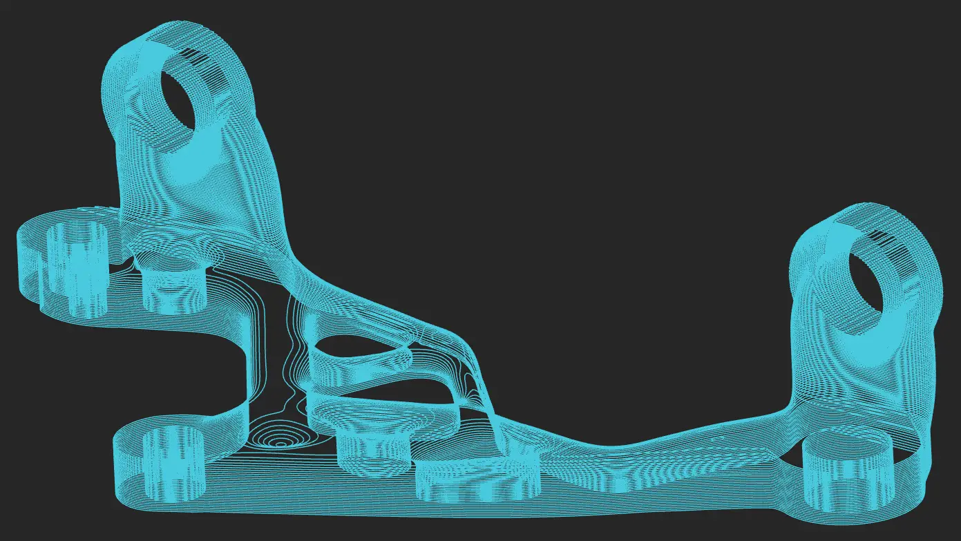
5. Topology optimization and lightweighting
Additive enables organic geometries that are impossible to mill:
- Internal lattices that cut weight while preserving stiffness (typically –40% weight at equal stiffness).
- Assembly consolidation: multiple parts merged into a single printed component.
- Conformal channels that follow the surface of the part (mold cooling, ducts).
6. Threads, inserts and fits
- Directly printed threads work up to M6; above that, use heat-set inserts or helical thread inserts (Helicoil).
- For moving fits, allow a diametral clearance of 0.2–0.3 mm in FDM and 0.1 mm in MSLA.
7. Common mistakes to avoid
- Copying a CNC drawing without rethinking it.
- Ignoring FDM/CFC anisotropy.
- Specifying needlessly tight tolerances on non-functional surfaces.
- Skipping the DfAM phase on the assumption that "it's only a prototype anyway."
A good DfAM analysis cuts costs by 20–40% and improves component performance. Send us your CAD for a free DfAM analysis or explore our design consulting services.