Technologies
Metal 3D Printing (LPBF): A Practical Guide
When LPBF metal 3D printing beats CNC machining and casting, the design rules that matter, and when a PEEK or CFC part can replace the metal one.
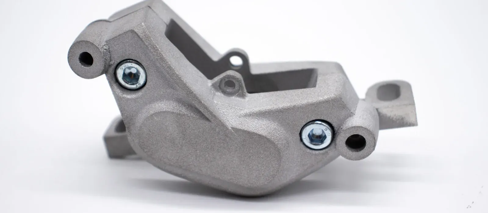
Metal 3D printing by LPBF (Laser Powder Bed Fusion, also called DMLS or SLM) melts metal powder layer by layer with a laser and produces dense metal parts with properties comparable to wrought material. It pays off when a part has internal channels, lattice structures or shapes that CNC machining and casting cannot produce, or when you need a few parts without tooling. For simple prismatic parts and high volumes, machining and casting are usually cheaper.
How laser powder bed fusion works
The part is built in 20–60 µm layers inside a sealed chamber under argon. For each layer, a recoater blade spreads the metal powder, a fiber laser steered by galvanometer mirrors melts the part's cross-section, and the platform drops by one layer. LPBF is the generic name, classified by the ISO/ASTM 52900 standard as PBF-LB/M; DMLS and SLM are trade names for the same principle.
The part grows welded to the build plate through supports, which anchor it and draw off the heat. Typical relative density is above 99.5%.
When it beats CNC machining and casting
It makes sense when geometric complexity, not quantity, drives the cost of the part. An indicative comparison:
| Criterion | LPBF | CNC machining | Casting |
|---|---|---|---|
| Internal channels and lattices | yes, including curved and conformal | straight drilled holes only | limited, needs cores |
| Dedicated tooling | none | fixturing and CAM programming | pattern and mold |
| Best-fit quantity | one-offs and short runs | one-offs to mid-size runs | high volumes |
| Simple prismatic parts | rarely cost-effective | usually the cheapest | depends on volume |
| Tight tolerances | with finish machining | yes | with finish machining |
Typical applications:
- mold inserts with conformal cooling channels;
- manifolds, nozzles and fluid-handling components;
- brackets lightweighted through topology optimization;
- assembly consolidation: several components redesigned as a single part;
- out-of-production spare parts, functional prototypes and short runs.
When it doesn't pay off
Metal printing is the wrong choice when the part is easy to cut from bar or plate stock. A prismatic component with straight holes and flat faces almost always costs less on a CNC machine. The same goes for high volumes, where a mold or a CAM program is amortized over many parts.
Size matters too: the industrial LPBF systems we use have a build volume of up to 400 × 400 × 400 mm; beyond that, the part has to be split or made with another process. Often the best answer combines both processes: metal printing for the geometry, machining for the functional surfaces.
Design rules that matter
The guidance below is indicative; we check it against your CAD as part of our DfAM consulting.
- Overhangs and supports. Surfaces inclined at less than about 45° to the build plate need supports that must be removed and leave witness marks. Chamfers and self-supporting angles instead of flat overhangs cut cost and lead time.
- Holes. Small horizontal holes print without supports; larger ones are best drawn as teardrops or machined after printing.
- Walls and fine features. The minimum feature is 0.75 mm and thin layers allow thin walls, but the minimum wall thickness depends on height, alloy and function, so check it before you freeze the design.
- Internal channels and powder. Every cavity needs openings so unmelted powder can be cleared after the build.
- Orientation. It decides where supports go, which surfaces come out rougher and how long the build takes, so choose it together with the functional surfaces.
- Residual stress. Rapid melting and cooling builds up stress in the part; keeping cross-sections as uniform as possible helps limit distortion.
Post-processing: from build plate to finished part
After printing, the part is stress-relieved while still on the plate, then separated, cleared of supports and finished. Typical dimensional accuracy is ±0.2% (minimum ±0.1–0.2 mm); for tighter tolerances the functional surfaces are machined. That is why your drawing should include machining stock on the surfaces to be machined. Any further heat treatment and surface finishing depends on the alloy and is agreed at the quote stage.
When a high-performance polymer or CFC can replace the metal part
If a part only needs to be metal for strength or stiffness, a high-performance polymer or a composite can often do the same job at a lower weight. PEEK handles high temperatures and aggressive chemicals; the full comparison is in our guide PEEK vs Ultem vs PPS. Continuous carbon fiber (CFC) reaches tensile strength of up to 900 MPa along the fiber, with specific stiffness comparable to aluminum; see our guide to metal replacement with CFC.
Metal remains the right choice beyond the thermal limits of polymers, on surfaces that face heavy wear, or when the spec calls for it. Otherwise, ask for the comparison: FDM and CFC run in our labs in Brescia, with an Express lane for prototypes.
Where to start
Upload your CAD as STEP or STL through the quote form; submitting it automatically activates our standard NDA. Tell us the alloy you need or the performance you expect (mechanical strength, operating temperature, corrosion resistance, weight), the quantity and the surfaces with critical tolerances. Within 24 business hours you receive a quote with the alloy, process and lead time, plus a free basic DfAM review. If the part could be made in a polymer or composite instead, we say so in the same quote. Full specs are on the metal 3D printing page.